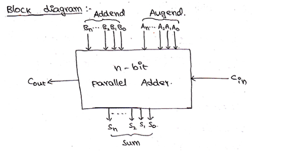

#4 BIT PARALLEL ADDER FULL#
A 4 to 1 line multiplexer has 4 inputs and 1 output line.In our experiment,we use IC 74153(Multiplexer) and IC 7404(NOT gate) for implementing the full adder. Multiplexer is also called a data selector,whose single output can be connected to anyone of N different inputs. A multiplexer is also called a data selector. When M 0, the circuit is an adder, and when M 1, the circuit.

Setting up AWS for Airflow parallel tasks. A 4-bit adder-subtractor circuit is shown in fig 4. 4-bit ripple carry adder is used for adding two. Multiplexers are mainly used to increase the amount of data that can be sent over the network within a certain amount of time and bandwidth. For example, a 4-bit adder can be parameterized to accept a value for the. Ripple carry adder is a combinational logic circuit used for the purpose of adding two n-bit binary numbers. A multiplexer of 2n inputs has n select lines, which are used to select which input line to send to the output. In electronics, a multiplexer (or MUX) is a device that selects one of several analog or digital input signals and forwards the selected input into a single line. The output carry is designated as Cout and the normal output is designated as S. When a full adder logic is designed we will be able to string four of them together to create a 4 bit adder and cascade the carry bit from one adder to the next. The first two inputs are A and B and the third input is an input carry designated as Cin. The full adder accepts two inputs bits and an input carry and generates a sum output and an output carry. The half adder accepts two binary digits on its inputs and produce two binary digits outputs, a sum bit and a carry bit. Our construction demonstrates that the addition of n-bit. Half Adders are the most basic of the adders. In 5 we use the results of 4 to give a simple and regular layout for carrying computation. In modern computer adder resides in the arithmetic logic unit (ALU). The circuit uses a controlled adder/subtractor circuit. An adder is digital circuit that perform addition of numbers. Abstract- In this paper a 4 bit parallel adder/subtractor circuit has been designed and analyzed.


 0 kommentar(er)
